Whether or not there is a super-boundary or defect reported at a specific location, the same data can be properly filtered and used to monitor minor defect occurrence trends to achieve effective control of the printing process. The minimum, maximum, and average amount of solder paste found in the pad gap can be saved after each device inspection. The same measurement can also be made for bridged gap measurements. In doing so, not only can effective process control and trend analysis be achieved, but it can also provide a means of fine-tuning detection parameters based on historical performance and actual product requirements, which is better than "through tests - finding errors - subjective judgments" The usual detection mode.
Other preventive measures
An additional source of prevention information can be provided through the detection of templates. Because the template is loaded into the printer during production, a separate AOI device cannot detect the template. Since the stencil inspection and solder paste stencil printing processes are mutually exclusive within the press, excessive or unnecessary stencil detection must be avoided to save time.
Here again to mention, for the judgment of the trend, and to identify possible causes of the defects found on the PCB, it is sufficient to set good sampling, and it is reasonable that the template, which is likely to produce defects, is also included. Dynamic targets may include self-triggering checks at the appropriate locations on the template that are directly related to the occurrence of defects on the PCB (either present or future) or the development of defects. Additional template checks will help identify and perform the most appropriate corrective actions in an appropriate manner.
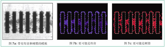
Figure 7a shows a template contaminated with solder paste and resin (flux). This situation reduces the clarity of printed graphics and, if left alone, may eventually lead to the type of (bridge) defect we are trying to detect and avoid on the PCB. Fig. 7b is a layered structure-based solder paste image of the template of Fig. 7a, which highlights the printing of the solder paste on the specific opening and template surface. Solder paste remaining in the opening is often associated with the lack of solder paste at the corresponding location on the board, and vice versa. Residues of solder paste on the underside of the stencil will prevent good contact between the pad and the opening, resulting in poor solder paste print patterns, increased pattern width and height, and more scattered solder paste entering the gap between the stencil and pad within the area. Figure 7c shows a region more like a resin than a solder paste. In order to automatically configure and initiate the most appropriate corrective action (in this example, an appropriate stencil wipe is required), detailed information such as this is required.
Conclusion - Other findings
Accurate bridging inspection is a key tool not only for the detection of today's very common SMT printing defects, but also useful for correcting unfavorable trends in the process. Because of a relatively inconspicuous solder paste pattern in the gap, it is possible to provide a clear path for the bridging pattern across the gap, and vice versa. In order to reliably determine the true bridge-like pattern for the process, the gap within the solder paste pattern and (bridge) span measurement is necessary.
In the repeatability test, due to the measurement content
The relationship between the difference and the amount of data, the measurement of the solder paste pattern in the gap is originally easier than the gap measurement. The repeatability of part of the gap measurement is programmed into the device's bridge detection sensitivity influence parameters. In the initial trial, we used the sensitivity considered to be a high level, although the lower sensitivity setting proved to be more suitable in practical applications. When the bridging detection sensitivity is set to "high," and only thin beams and bridged spans exist, the result is the worst repeatability (under 3 standard deviations). In this example, fortunately, the possibility of bridging related defects is small, and the boundaries of the span can be adjusted to avoid unnecessary detection of short solder paste fines. In any case, for successful process control (SPC), statistical analysis will still reveal obvious trends. Of course, the more realistic bridge shapes provided at any sensitivity setting, the more repeatable the measurement of span results. Our test results have been published.
Additional prevention information can be obtained through stencil detection, which helps identify and perform the most effective adjustments at high production speeds to maintain rigorous process control.
Bridge detection can only succeed if the paste pattern is separated from the background image and the correct method is used for the test. Once the correct solder paste pattern has been established, this analysis method can provide useful and reliable bridge characteristics measurements for the board assembly process.
Hesco Barrier,Hesco Bastion Wall,Hesco Gabion,Hesco Fence
Anping County Hua Guang Wire Mesh Production Co.,Ltd , https://www.hgwirefence.com